Stretcher Bars
Fixed Stretcher Bars
DTS can offer the full range of insulated and non-insulated Stretcher Bars to suit the following sections:
- Full Depth Vertical & Inclined S&C layouts of BR109, BS110A, BS113A & CEN56 rail section running lines.
- 95RBH running rail.
Should you require further information please contact info@directtracksolutions.co.uk
Tubular Stretcher bars


Developed to replace ‘fixed’ and ‘adjustable’ track stretcher bars on UK railway.
The Tubular Stretcher Bar offers improved performance, greater safety and a reduced whole life cost.
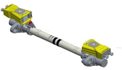
The TSB consists of:
- 2 x Drive connection Brackets
- 2 x Motion units
- 1 x tube
- 2 x Switch rail brackets
Similar to the first image.
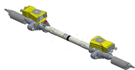
The 1st TSB within a switch is noticeable different as it includes kicking straps which prevent the switch rails from rising with respect to the stock rails. Similar to the second image.
The Tubular Stretcher bar is compatible with most :
- rail section
- BR109lb, BS110A, BS113A, CEN56, UIC54, CEN60
- switch designs
- BR Inclined, Vertical full depth, Vertical shallow depth, Switch Diamonds, NR60 MKii (Plain leads)
- POE.
- RCPL (MKi, MKii and IBCL), HW, M63.
There are some Switch and POE designs that are not suitable for TSB’s.
Should you require further information please contact info@directtracksolutions.co.uk
Motion Units
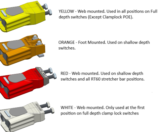
The motion units on the TSB are colour coded and denote the type of rail section and POE to which the stretcher bar can be fitted.

Should you require further information please contact info@directtracksolutions.co.uk
Tubes
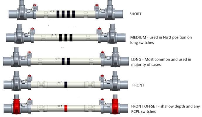
There are 5 different variants of tube, that vary in length and position within the switch. They are donated by a number of stripes and or colour of stripe. As per below.

Should you require further information please contact info@directtracksolutions.co.uk